|
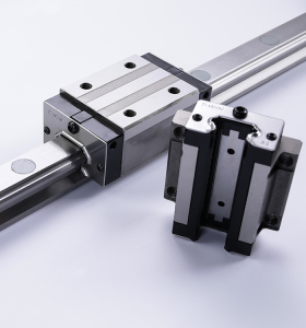
Design principles for precision guide rail installationTaiwen Precision Machine will introduce the installation and design principles of precision guide rails to you For precision guides with high requirements for geometric accuracy, motion accuracy, and positioning accuracy (such as guides for CNC machine tools and measuring machines), the following principles should be followed in design: The principle of error compensation meets the following three requirements to enable the guide rail system to achieve mutual error compensation: (1) Intermediate elastic links, such as rolling plastic strips or fluid films, must be installed between the guide rails. (2) There should be sufficient pre tension between the guide rails to compensate for contact errors. (3) The manufacturing error of the guide rail should be less than the deformation of the intermediate elastic body (component).
2. The principle of non-interference in accuracy is that during manufacturing and use, the various accuracies of the guide rail do not affect each other in order to achieve high accuracy. For example, the straightness of the rectangular guide rail and the straightness of the side guide rail do not affect each other during manufacturing; The changes in the lateral dimensions of the flat V guide rail combination guide rail will not affect the working accuracy of the guide rail. When designing guide rail pairs, the dynamic and static friction coefficients should be as close as possible to the contact surface of the guide rail, in order to achieve high repeated positioning accuracy and low-speed stability. Rolling guide rails, ordinary sliding guide rails embedded with plastic sheets or covered with plastic sheets have small friction coefficients and similar static and dynamic friction coefficients. 4. The principle of automatic bonding of guide rail pairs is to ensure high precision of the guide rail, and the guide rail pairs must have the characteristic of automatic bonding. Horizontal guide rails can be attached by the weight of moving components; Other guide rails must be fitted with additional spring force or roller pressure. 5. The principle of full contact is that the length of the fixed guide rail must ensure that the moving guide rail is in contact with the entire length of the fixed guide rail at the two extreme positions of the maximum travel (without exceeding the fixed guide rail), to ensure that the guide rail pair always makes full contact during the contact process. 6. Compensation for force deformation and thermal deformation principle: When the guide rail and its supporting components are subjected to force or temperature changes, when designing the guide rail and its supporting components, efforts should be made to make them deform into the required shape. Like the crossbeam guide rail of a gantry machine tool, it is made into a convex shape to compensate for the bending deformation caused by the weight of the spindle box (or tool holder). |


